- 您现在的位置:买卖IC网 > Sheet目录987 > LD4T06P0 (Red Lion Controls)TIMER 6 DIGIT 4.0" 120VAC RED
�� �
�
�Command� Response� Time�
�The� meter� can� only� receive� data� or� transmit� data� at� any� one� time� (half-duplex�
�operation).� During� RS232� transmissions,� the� meter� ignores� commands� while�
�transmitting� data,� but� instead� uses� RXD� as� a� busy� signal.� When� sending�
�commands� and� data� to� the� meter,� a� delay� must� be� imposed� before� sending�
�another� command.� This� allows� enough� time� for� the� meter� to� process� the�
�command� and� prepare� for� the� next� command.�
�At� the� start� of� the� time� interval� t� 1� ,� the� computer� program� prints� or� writes� the�
�string� to� the� com� port,� thus� initiating� a� transmission.� During� t� 1� ,� the� command�
�At� the� beginning� of� time� interval� t� 3� ,� the� meter� responds� with� the� first�
�character� of� the� reply.� As� with� t� 1� ,� the� time� duration� of� t� 3� is� dependent� on� the�
�number� of� characters� and� baud� rate� of� the� channel.� At� the� end� of� t� 3� ,� the� meter� is�
�ready� to� receive� the� next� command.�
�t� 3� =� (10� times� the� #� of� characters)� /� baud� rate�
�The� maximum� serial� throughput� of� the� meter� is� limited� to� the� sum� of� the�
�times� t� 1� ,� t� 2� and� t� 3� .�
�NO� REPLY� FROM� METER�
�characters� are� under� transmission� and� at� the� end� of� this� period,� the� command�
�terminating� character� (*� or� $)� is� received� by� the� meter.� The� time� duration� of� t� 1�
�is� dependent� on� the� number� of� characters� and� baud� rate� of� the� channel.�
�Command�
�String�
�Transmission�
�Meter�
�Response�
�Time�
�t� 1� =� (10� times� the� #� of� characters)� /� baud� rate�
�Ready�
�t� 1�
�t� 2�
�Ready�
�At� the� start� of� time� interval� t� 2� ,� the� meter� starts� the� interpretation� of� the�
�command� and� when� complete,� performs� the� command� function.� This� time�
�interval� t� 2� varies.� If� no� response� from� the� meter� is� expected,� the� meter� is� ready�
�to� accept� another� command.�
�If� the� meter� is� to� reply� with� data,� the� time� interval� t� 2� is� controlled� by� the� use�
�of� the� command� terminating� character.� The� ‘*’� terminating� character� results� in�
�RESPONSE� FROM� METER�
�a� response� time� of� 50� msec.� minimum.� This� allows� sufficient� time� for� the�
�Ready�
�t� 1�
�t� 2�
�t� 3�
�Ready�
�Timing� Diagram� Figure�
�release� of� the� sending� driver� on� the� RS485� bus.� Terminating� the� command� line�
�with� ‘$’� results� in� a� response� time� (t� 2� )� of� 2� msec.� minimum.� The� faster� response�
�time� of� this� terminating� character� requires� that� sending� drivers� release� within� 2�
�msec.� after� the� terminating� character� is� received.�
�Command� First�
�Terminator� Character�
�Received� of� Reply�
�Reply�
�Transmission�
�Time�
�Communication� Format�
�Data� is� transferred� from� the� meter� through� a� serial� communication� channel.�
�In� serial� communications,� the� voltage� is� switched� between� a� high� and� low� level�
�at� a� predetermined� rate� (baud� rate)� using� ASCII� encoding.� The� receiving� device�
�reads� the� voltage� levels� at� the� same� intervals� and� then� translates� the� switched�
�levels� back� to� a� character.� The� voltage� level� conventions� depend� on� the� interface�
�standard.� The� table� lists� the� voltage� levels� for� each� standard.�
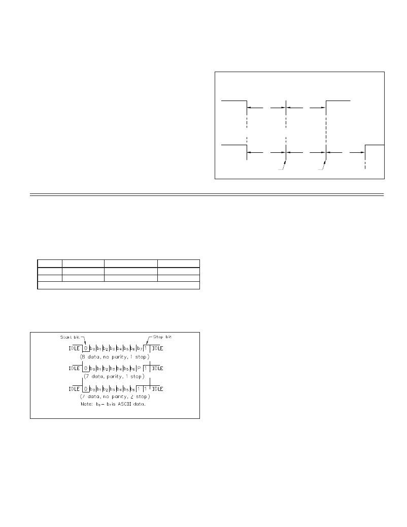
�Start� Bit� and� Data� Bits�
�Data� transmission� always� begins� with� the� start� bit.� The� start� bit� signals� the�
�receiving� device� to� prepare� for� reception� of� data.� One� bit� period� later,� the� least�
�significant� bit� of� the� ASCII� encoded� character� is� transmitted,� followed� by� the�
�remaining� data� bits.� The� receiving� device� then� reads� each� bit� position� as� they� are�
�transmitted.�
�Parity� Bit�
�LOGIC�
�1�
�INTERFACE� STATE�
�mark� (idle)�
�RS232*�
�TXD,RXD;� -3� to� -15� V�
�RS485*�
�a-b� <� -200� mV�
�After� the� data� bits,� the� parity� bit� is� sent.� The� transmitter� sets� the� parity� bit� to�
�a� zero� or� a� one,� so� that� the� total� number� of� ones� contained� in� the� transmission�
�0� space� (active)� TXD,RXD;� +3� to� +15� V�
�*� Voltage� levels� at� the� Receiver�
�a-b� >� +200� mV�
�(including� the� parity� bit)� is� either� even� or� odd.� This� bit� is� used� by� the� receiver�
�to� detect� errors� that� may� occur� to� an� odd� number� of� bits� in� the� transmission.�
�However,� a� single� parity� bit� cannot� detect� errors� that� may� occur� to� an� even�
�Data� is� transmitted� one� byte� at� a� time� with� a� variable� idle� period� between�
�characters� (0� to� ?� ).� Each� ASCII� character� is� “framed”� with� a� beginning� start� bit,�
�an� optional� parity� bit� and� one� or� more� ending� stop� bits.� The� data� format� and�
�baud� rate� must� match� that� of� other� equipment� in� order� for� communication� to�
�take� place.� The� figures� list� the� data� formats� employed� by� the� meter.�
�number� of� bits.� Given� this� limitation,� the� parity� bit� is� often� ignored� by� the�
�receiving� device.� The� LD� Timer� ignores� the� parity� bit� of� incoming� data� and� sets�
�the� parity� bit� to� odd,� even� or� none� (mark� parity)� for� outgoing� data.�
�Stop� Bit�
�The� last� character� transmitted� is� the� stop� bit.� The� stop� bit� provides� a� single� bit�
�period� pause� to� allow� the� receiver� to� prepare� to� re-synchronize� to� the� start� of� a�
�new� transmission� (start� bit� of� next� byte).� The� receiver� then� continuously� looks�
�for� the� occurrence� of� the� start� bit.� If� 7� data� bits� and� no� parity� is� selected,� then� 2�
�stop� bits� are� sent� from� the� meter.�
�Character� Frame� Figure�
�13�
�发布紧急采购,3分钟左右您将得到回复。
相关PDF资料
LFSTBEB7361
BOARD DEV ACCELEROMETER MMA7361L
LFSTBEB7455
BOARD DEV ACCELEROMETER MMA7455L
LFSTBEB8450
BOARD DEV ACCELEROMETER MMA8450
LFSTBEB845X
EVAL BOARD FOR MMA845XQ
LH1518AT
RELAY SSR SPST 250V 300MA 6DIP
LI12-1A79
RELAY REED SPST 1A 12V
LK1AF-24V
RELAY GEN PURPOSE SPST 5A 24V
LKG1AF-24V-16-1
RELAY GEN PURPOSE SPST 16A 24V
相关代理商/技术参数
LD50
制造商:General Tools 功能描述:Deluxe Lightning Detector 制造商:General Tools 功能描述:DETECTOR LIGHTNING
LD-50
制造商:API TECHNOLOGIES 功能描述: 制造商:API Technologies Corp 功能描述:
LD5000
制造商:WTE 制造商全称:Won-Top Electronics 功能描述:50A 10mm LUCAS TYPE PRESS-FIT DIODE
LD5001
制造商:WTE 制造商全称:Won-Top Electronics 功能描述:50A 10mm LUCAS TYPE PRESS-FIT DIODE
LD5002
制造商:WTE 制造商全称:Won-Top Electronics 功能描述:50A 10mm LUCAS TYPE PRESS-FIT DIODE
LD5003
制造商:WTE 制造商全称:Won-Top Electronics 功能描述:50A 10mm LUCAS TYPE PRESS-FIT DIODE
LD5004
制造商:WTE 制造商全称:Won-Top Electronics 功能描述:50A 10mm LUCAS TYPE PRESS-FIT DIODE
LD5005
制造商:WTE 制造商全称:Won-Top Electronics 功能描述:50A 10mm LUCAS TYPE PRESS-FIT DIODE